


If your push-to-connect air fittings are leaking in service, the first useful distinction is where the air is escaping: at the tube entry, at a threaded port, through a damaged body, or from a nearby component. These locations lead to different checks. Repeatedly pushing, twisting or tightening the nearest fitting can hide the original symptom and create additional damage.
This guide helps a competent maintenance person structure a diagnosis and helps a buyer provide useful information for support. It is not a model-specific repair procedure. Any physical work must follow the equipment’s safe-isolation procedure and the instructions for the actual fitting and tubing. Do not disconnect, loosen or manipulate a pressurised connection.
Scope and Safety Before Any Check
Make the equipment safe before touching the connection. HSE’s maintenance guidance calls for isolation of relevant energy sources, protection against unintended reconnection, release of stored energy and support of components that could move or fall.1 Follow your site’s complete procedure; switching off an electrical control alone should not be taken as proof that pneumatic energy is gone.
SMC’s published precautions similarly require supply pressure to be cut and residual compressed air exhausted before removal, with precautions against unexpected actuator movement.2
If you cannot establish safe isolation, do not proceed with hands-on inspection. Escalate to the person responsible for the equipment. A stopped production cycle, a silent compressor or one gauge reading is not a substitute for the required verification at the work area.
A leak observed through an already authorised operating-state inspection may be documented without changing the connection. Any additional live testing needs its own approved method and competent supervision. Do not search for escaping air with fingers or loosen a connection to “see whether pressure remains.”
Record the Fitting and Tubing Details
Before changing anything, record the exact fitting model and the tube’s identification, size and material information. Keep photographs of the overall arrangement, readable markings and the suspected area, obtained without entering an unsafe zone.
A push-in air fitting leak can be misdiagnosed when only the fitting is identified. The supplied catalogue’s fitting precautions call attention to tube outside-diameter tolerance, a square tube end, an undamaged outer surface and a tube end that is not oval. They also warn against unsuitable loading and explain that incorrect tightening can cause leakage or damage.3
These are reasons to inspect the fitting–tube combination, not permission to assume every tube of a similar apparent size is suitable. Use the actual model’s accepted tube specification. If the tube has no identifiable specification, record that uncertainty before purchasing a replacement.
Record the Correct Connection Layout
The series name helps organise the report, but it does not diagnose the leak. Within the selected PneuDock content scope, use the following distinctions when recording an already identified component.4
| Identified series | Connection layout to record | Avoid this reporting mistake |
|---|---|---|
| PCF | One tube entry and one female-thread connection | Reporting only “the PCF leaks” without locating the tube or threaded interface |
| PC | One tube entry and one male-thread connection | Copying PCF’s thread gender into the report or assuming a sealing method from the code |
| PU | Two in-line tube entries | Searching for a threaded joint on the described tube-to-tube union |
| PV | Two tube entries in a right-angle layout | Confusing the part with a PL threaded elbow or a flow-control valve |
For example, a report naming PV12 should distinguish its two tube-entry locations rather than inventing a threaded-port symptom. A report naming PCF8-02 should identify whether the observed location is the tube side, the threaded connection or somewhere else. These are reporting examples, not statements that either model has a known defect.
For a replacement inquiry, PCF series information and PC series information identify the intended connection forms. They do not replace the actual equipment manual, supplier-approved model drawing or the safe-isolation requirements above. Do not use a product illustration to infer insertion depth, torque, an internal seal or an approved repair.
Describe Where and When the Leak Appears
Start pneumatic fitting leak diagnosis with a location-and-evidence table. The actions below are conditional checks after verified isolation, not instructions to dismantle any product against its manual.
| Observation | Possible area to investigate—not a confirmed cause | Appropriate next step |
|---|---|---|
| Leakage has been located at the tube entry | Tube seating, outer-surface condition, roundness, size or suitability | Compare the isolated tube/fitting combination with the actual instructions. Correct or replace only as those instructions permit. |
| Leakage has been located at the threaded port | Thread identity, approved sealing arrangement, damaged port or installation condition | Confirm both mating specifications and the prescribed installation method. Do not apply an arbitrary extra turn. |
| Body is visibly cracked or deformed | Mechanical damage or an unsuitable condition | Do not return it to service. Have the cause and replacement requirement reviewed. |
| Leakage recurs after a permitted tube replacement | Routing/load or an unresolved fitting, tube or application mismatch | Stop treating the tube end as the only explanation; review the entire connection with technical support. |
| Sound is near a valve or exhaust component, but the location is uncertain | The source may not be the tube fitting | Identify the emitting component through the authorised diagnostic method. Do not block an exhaust or replace the nearest part by guesswork. |
The table deliberately separates observations from conclusions. “Leak noticed after maintenance” is an observation. “The seal is defective” is a diagnosis that still needs evidence.
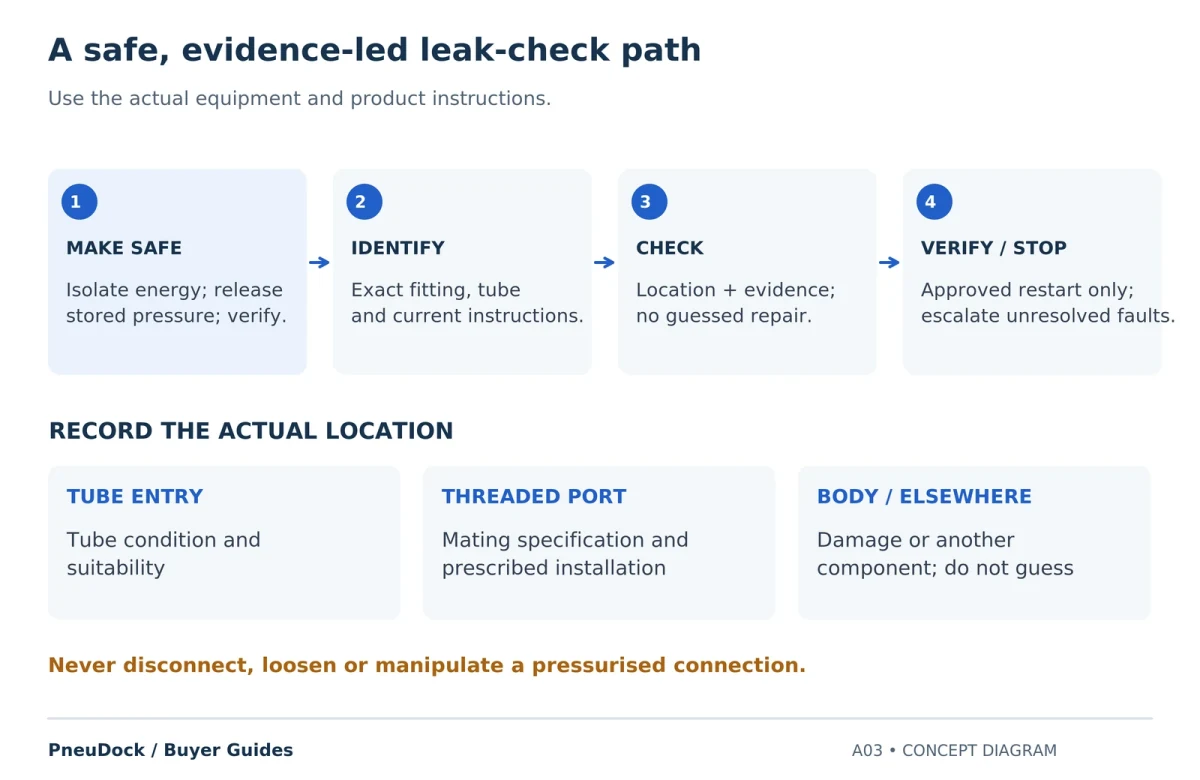
Record timing as well as location: first noticed after installation, during an existing operating phase, or following a documented maintenance change. Do not recreate an unsafe condition just to complete a report.
Compare Against the Correct Product Instructions
Effective push-to-connect fitting troubleshooting uses the instructions for the selected product, not a general internet insertion depth, tightening torque or sealant recommendation.
For a connection that the manual allows to be serviced, the relevant checks may include the following:
Tube end and seating. Check the stated tube specification, end condition and insertion/retention instructions. The supplied fitting precautions describe a square cut, sound external surface and a retention check after connection.3 Do not turn this into a universal cut-back length or insertion measurement. Those values, and whether a damaged end can be re-prepared, require the actual instructions and enough serviceable tubing.
Threaded installation. Identify the mating threads and sealing design before changing the joint. The same catalogue distinguishes installation requirements and warns that both insufficient and excessive tightening can be problematic.3 “Add more sealant” is not a diagnosis, and sealant intended for a threaded interface does not belong on the tube’s gripping/sealing surface unless the manufacturer specifically instructs it.
Routing and external loading. Preserve the route in your report. A connection being used to hold a line under tension is a different situation from a freely routed, supported line. Ask for the permissible arrangement instead of bending or forcing the connection until the symptom temporarily changes.
Damaged or uncertain parts. If a body, release mechanism or mating surface is visibly damaged, or the model cannot be established, obtain a suitable replacement decision. Do not sand, glue, improvise an internal seal or open a non-serviceable fitting. HSE advises against using faulty equipment, and the SMC common precautions do not authorise product modification.12
After any authorised correction, a competent person should follow the equipment’s controlled restart and verification procedure. A repair is not established merely because the connection felt secure while isolated. If the permitted test still fails, stop and escalate rather than repeating increasingly forceful adjustments.
Request Model-Specific Support
Send air fitting leak information that another person can review without guessing. A useful report identifies:
| Field | What to record |
|---|---|
| Equipment and connection | Identifiable location; fitting model and source |
| Tube | Marking, specification, material and size information |
| Symptom | Where the leak was identified and by what approved method |
| Timing | When first noticed; known changes beforehand |
| Operating context | Relevant recorded conditions—not invented estimates |
| Inspection | What the competent person checked after isolation |
| Evidence | Clear photographs, current manual and drawing revision |
| Outcome needed | Technical clarification, approved replacement or other support |
Hypothetical example: a recently installed elbow leaks at its tube entry. After isolation, the authorised technician finds a damaged outer tube surface near the end. A useful report records that finding and the applicable instruction. It does not assert that all leaks are caused by tube damage, or that replacing the tube necessarily resolves an internal fitting fault.
For replacement sourcing, keep the old model and the proposed alternative separate. A similar outline does not establish an equivalent connection or operating envelope.
Questions Before Returning to Service
Should I tighten the fitting while listening for the leak to stop?
No. Make the equipment safe and use the prescribed installation procedure. Arbitrary tightening can turn an uncertain joint into a damaged one.
Can a leaking tube connection be repaired with tape or glue?
Do not improvise a repair on the gripping or sealing interface. Use only the correction or replacement procedure permitted for the actual product.
What if the exact fitting cannot be identified?
Keep it out of an assumed repair pathway. Provide the markings, tube information and equipment documentation to the responsible technical person or supplier and obtain a verified specification.
Take the Next Step
Use PneuDock’s Contact route for an existing product-support question, or Start Your Inquiry for a replacement request. Include the model, tube details and evidence above. The tubing information guide can help you describe the mating tube without guessing dimensions.
Sources and Scope
-
UK Health and Safety Executive, Maintenance of work equipment, safe isolation, stored energy, competence and damaged equipment. This is general safety guidance; local requirements and the site procedure must also be followed.
-
SMC, TU/TIUB tubing catalogue, physical pages 5–6, Safety Instructions and Common Precautions. Referenced for general manufacturer safety principles, not as a repair manual for a PneuDock item.
-
Supplied pneumatic catalogue, physical page 11, printed page 013, common fitting precautions: tube condition, removal without pressure, loading and installation. Scope and limitations are recorded in the technical source notes. The actual selected fitting’s current instructions take precedence.
-
PneuDock selected fitting-series reference, limited to the four series and twelve model references in the current product-content plan. These references do not establish stock, thread standard, materials, dimensions or interchangeability.
[…] material requirement, total length and units. For an existing leaking connection, read the leaking push-to-connect fitting information guide rather than substituting a guessed tube […]