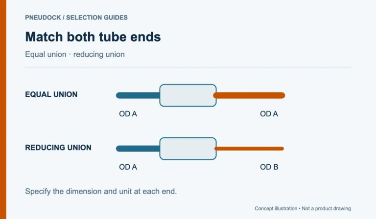


The difference in pneumatic meter-in vs meter-out flow control is the direction of the flow being restricted. Meter-in restricts air entering the actuator chamber. Meter-out restricts air leaving it. Choosing a speed controller therefore requires the circuit function and flow direction as well as the tube and thread sizes.
A matching elbow shape does not establish that two controllers work the same way. Read the model-specific pneumatic symbol and identify its controlled and free-flow paths before approving a part.
What a one-way pneumatic flow control valve does
A one-way flow controller combines adjustable restriction in one direction with a check-valve path allowing freer flow in the reverse direction. Its installed orientation determines which path the cylinder uses during each movement. A simple throttle without that check-valve function is a different configuration.
SMC’s AS metal-body catalogue distinguishes meter-in and meter-out options and separately identifies throttle configurations. Its ordering designations apply to that series. Do not transfer the meaning of one manufacturer’s suffix to another supplier’s product code.
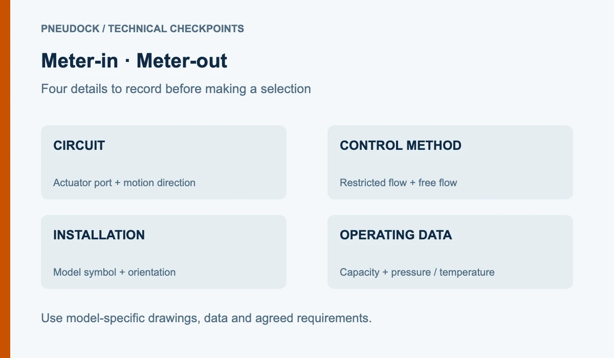
| Control method | Restricted flow | Information to record |
|---|---|---|
| Meter-in | Supply to the actuator chamber | Supply path, movement direction and load conditions |
| Meter-out | Exhaust from the actuator chamber | Exhaust path, opposite chamber and downstream restrictions |
| Bidirectional throttle | Restriction without a one-way bypass | Whether both directions are intended to be restricted |
Read pneumatic speed controller circuit symbols
Mark the actuator port on the drawing, then trace the airflow for extension and retraction separately. Identify the adjustable restriction and the parallel check valve. Record which physical connection faces the actuator. If the drawing and the replacement’s symbol cannot be reconciled, ask the equipment designer or supplier before ordering.
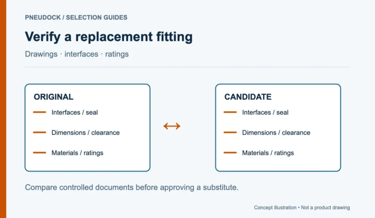
A useful approval sheet has three adjacent fields: the circuit excerpt, a photograph showing the installed orientation, and the proposed model’s symbol. That makes a direction mismatch easier to find than comparing product photographs alone.
Cylinder exhaust speed control selection
SMC’s Smooth Cylinders catalogue illustrates control circuits that use meter-in and meter-out control for specific motion requirements. These are circuit behaviors, not a promise that a particular external fitting will stabilize every load. Selection also depends on the actuator, load direction, pressure conditions and the rest of the circuit.
Before considering a replacement, describe whether the cylinder is horizontal or vertical, whether a load can drive the motion, and whether the observed issue occurs at startup or throughout the stroke. Have the responsible designer decide the required control method. A speed controller should not be assumed to provide load holding, safe isolation or protection against unexpected movement.
Match capacity and installation details
After the circuit function is agreed, check the controller’s tube connection, port thread, pressure-temperature limits and documented flow characteristics. Ask which flow direction a quoted capacity describes and under what test conditions it was measured. The nominal connection size is not a complete description of controllable flow.
Include space for the adjustment knob and any locking feature, access to the tube release collar and clearance around adjacent ports. Record whether adjustment must remain accessible after installation. Keep the manufacturer’s setting and commissioning procedure with the approved part; a remembered number of knob turns is not a transferable operating specification.
An illustrative replacement decision
A maintenance team needs a controller with the same tube size and apparent shape as an old fitting. Its initial request omits the restricted-flow direction. During review, the team adds the original circuit excerpt, cylinder port location and proposed replacement symbol. The supplier can then address the actual control function rather than quoting a visually similar elbow.
PneuDock’s PSL flow control fitting references are a starting point for an inquiry. State the required direction and operating conditions; the listed reference does not by itself establish a meter-in or meter-out configuration. Keep each proposed configuration separate using the pneumatic parts RFQ checklist.
Technical references
- SMC: AS metal-body speed controllers — control-method options and series-specific ordering information.
- SMC: Smooth Cylinders — application-specific meter-in and meter-out circuit examples. These references explain control concepts, not PneuDock product ratings.